
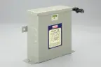
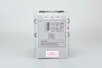



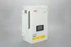
Static Var Generator

Product overview
Key benefits
Dynamic compensation
Dynamic reactive-power compensation.
Better power factor
Improved power factor under varying load conditions.
Smooth, stepless
Compensation without conventional capacitor-step switching.
Leading and lagging
Support for leading and lagging reactive-power conditions.
Optional load balancing
Three-phase load balancing, where supported by the selected model.
What is a Static Var Generator?
A Static Var Generator is a power-electronic reactive-power compensation device that controls the flow of reactive current in an electrical system. It continuously evaluates the relationship between voltage and current, determines the reactive-power requirement and adjusts its output accordingly.
An SVG is especially useful where reactive-power demand changes rapidly and conventional switched capacitor banks cannot provide sufficiently smooth or responsive correction.
How does an SVG work?
Measure
Current transformers and voltage measurements provide information about the electrical system’s operating condition.
Calculate
The controller evaluates the reactive-power requirement and determines the appropriate compensation current.
Compensate
The power converter supplies or absorbs controlled reactive current to move the system toward its power factor target.
Why choose Subodhan SVG solutions?
Responsive compensation for fluctuating loads
The SVG adjusts its reactive-current output as the load changes, beneficial for motor-driven systems, HVAC installations and variable production cycles.
Smooth control instead of discrete steps
Conventional APFC panels switch capacitor stages in steps. An SVG regulates its output electronically for finer adjustment within its rated capacity.
Support for leading and lagging power factor
Depending on system conditions, the SVG can provide inductive or capacitive reactive-power compensation.
Compact power-electronic architecture
SVG systems can offer installation and layout advantages compared with some conventional arrangements; actual space requirements depend on the model and cabinet design.
Designed for system integration
Proper CT placement, target power factor, network configuration and coordination with existing APFC equipment are important.
Typical applications
Applications
Application
Typical loads
Motors and industrial drives
Reactive-power demand that varies with operating load
HVAC and commercial buildings
Chillers, air handling and building services
Welding and manufacturing
Applications with rapidly varying electrical loads
Water and infrastructure
Pumping installations and utility infrastructure
Other potential sectors
Automotive, steel and metal, textiles, cement, pharmaceuticals, paper, data centres and industrial facilities with fluctuating reactive-power demand
SVG product features
Features
- Bidirectional reactive-power compensation: capacitive and inductive, according to system demand
- Continuous output regulation within the available reactive-power rating
- Configurable power factor targets where supported
- Fast electronic control for changing reactive loads within specified response capability
- Monitoring, alarms and protection functions as provided by the model
- Integration with existing electrical panels or dedicated SVG cabinets
- Optional load balancing on models designed for this function
Technical specifications
Static Var Generator (SVG)
Product
Static Var Generator
Primary function
Dynamic reactive-power compensation
Compensation modes
Inductive and capacitive
Voltage options
Available voltage classes by model
Capacity options
25–800 kVAr portfolio range, subject to model availability
Power factor control
Configurable target, subject to controller capability
Response time
As per the manufacturer-specified value for the selected model
Load balancing
Where supported by the selected model
Harmonic mitigation
Not the primary function; assess an AHF or a suitable hybrid model if required
Installation
Panel-mounted or cabinet-integrated configurations, as available
SVG versus conventional APFC
SVG versus conventional APFC
Parameter
Conventional APFC
SVG
Compensation method
Switched capacitor stages
Power-electronic current control
Adjustment
Discrete steps
Smooth adjustment within rated limits
Changing loads
Depends on step size and switching response
Designed for dynamic reactive loads
Leading / lagging control
Depends on bank and control arrangement
Bidirectional reactive compensation
Main consideration
Step sizing, switching and detuning
Converter rating, CT arrangement and operating limits
An SVG does not automatically eliminate harmonic distortion. Where harmonic currents are the primary concern, assess an AHF or suitable combined compensation solution.
SVG selection guide
Configurations available
- Establish existing power factor and reactive-power demand under different operating conditions.
- Identify the required target power factor and any utility requirements.
- Determine required compensation capacity in kVAr, including load variation and engineering margin.
- Check network voltage, phase configuration, CT location and existing APFC equipment.
- Evaluate harmonic levels, ambient temperature, ventilation, enclosure requirements and the need for load balancing.
- Confirm the selected SVG rating and control settings through engineering calculations and commissioning measurements.
Frequently asked questions
What is the main purpose of an SVG?
Can an SVG replace a conventional APFC panel?
It can replace some conventional reactive-power compensation arrangements if it has sufficient capacity and meets application requirements. A hybrid arrangement may suit other installations.
Can an SVG work with an existing APFC panel?
Is an SVG the same as an Active Harmonic Filter?
How do I calculate the required SVG capacity?
Need the right fit for your system?
Get the full specifications or talk to our team.